
The real, physical Cornell box.
From Modeling the Interaction of Light Between Diffuse Surfaces, by Goral et al 1984
Please, feel free to gather better data yourself and prove me wrong. If you do so I'll link to it!
Game developers are in love with screenspace ambient occlusion (SSAO). They're so in love with it that they do all sorts of crazy things. Amateur developers post screenshots where convex corners get brighter near the corner. Professional developers release games with bizarre halos and ugly artifacts (look at the floor behind the railing).
Even when they avoid those flaws, games with SSAO often still look wrong. And an easy thing to pull out from it: corners of rooms look weirdly dark.
I believe this is because people think the corners of rooms actually are dark, and they've allowed this belief to let them write code that produces unrealistic results.
More specifically, I attribute the failure of SSAO in these cases to some combination of four factors:
I am not an active graphics researcher, so I'm not going to set up a framework and show where these things went wrong. That's the job of people publishing SSAO papers and shipping SSAO in games.
For the same reason, the following discussion is not the most scientific nor at all thorough. Perhaps collecting more data would suggest I am wrong. But my personal visual experience doesn't match what people are rendering with SSAO, so I wanted to share that experience; to which end I collected some data.
In the following, everything is a photograph, not a rendering.
Photographs were taken using a Canon 5D Mk II, exported as JPEGs, using exposures ranging from a 1/80 to 1/8 a second. The original large JPEGs were downsampled by a factor of about four in each dimension using Adobe Photoshop. All images had their chroma channels blurred with a 16-wide gaussian in Photoshop (before downsampling) to reduce chroma noise artifacts in the long exposure images.
The ceiling of the apartment is a lighter, whiter color than the walls, so don't attribute that incorrectly to lighting.
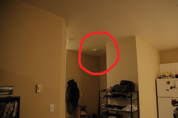
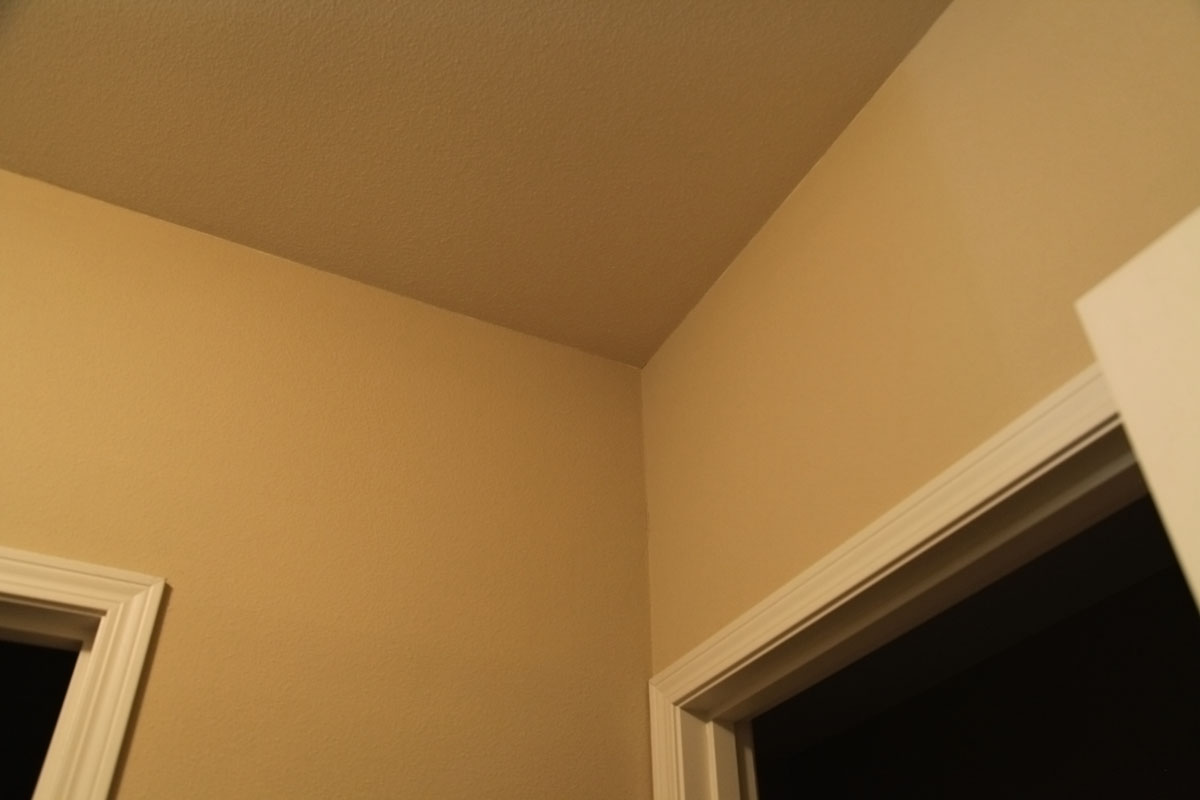
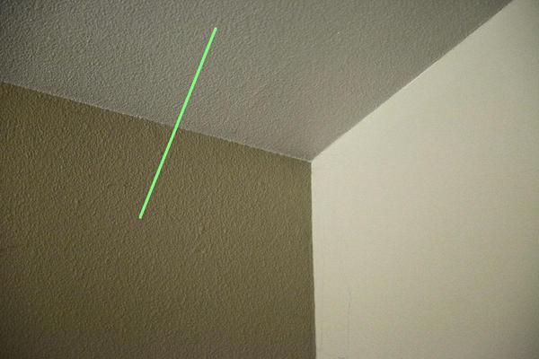
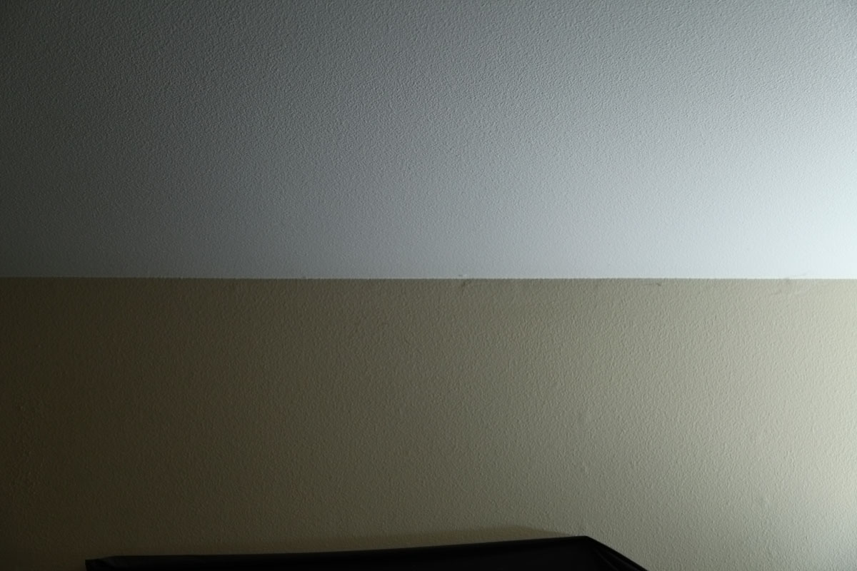
Let's start with a photograph that actually looks something like a common AO/SSAO rendering.
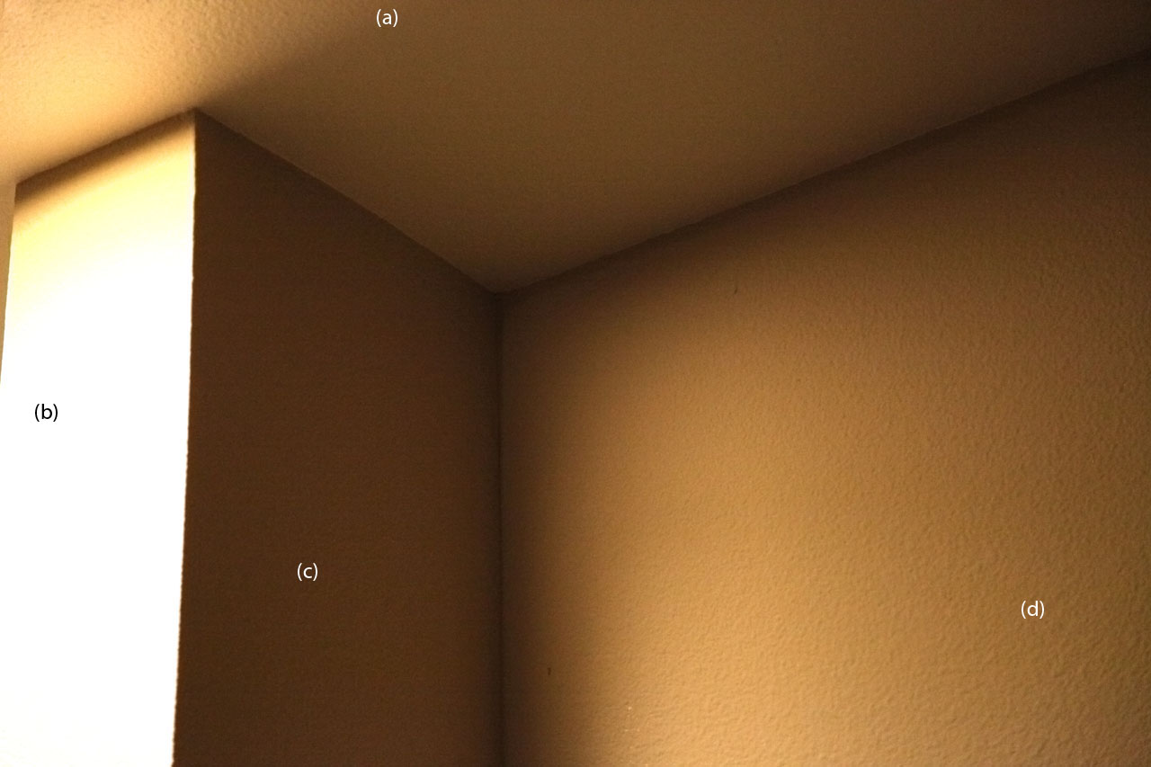
(This image has been digitally brightened to make the effect more visible.
Hopefully the brightening was gamma-preserving.)
I had to search my apartment quite a while to find a corner which looked like a typical SSAO rendered image. The thing is, that's not really what's going on here. Wall (c) cannot see the light, but wall (d) is quite exposed to it. The darkening on the left edge of the wall (d) isn't primarily due to AO (i.e. due to interreflection/radiosity effects); it's mostly due to a soft shadow from the light, which is just off the screen to the top left. The corner on the left, between wall (b) and wall (c), is casting a shadow, but it's very close to the light so it spreads out into a big soft shadow.
There are other edges that are getting darker as well, though. What about them?
The top edge of wall (d) is another shadow -- look at the top edge of the bright wall. The light source is recessed, so all of the light here is actually reflected light from the recession, and the lip of that recession causes the topmost parts of the wall to not receive that light. (All light falling on the ceiling is indirect, from the walls and floor and other objects in the room.)
What about the darkening-towards-the-edge effect on wall (c) as it reaches the right edge, or ceiling (a) as it reaches the edge along wall (d)? That appears to be an indirect lighting effect caused primarily by the Lambertian dot product; as a point approaches the center edge on wall (c), the bright portions of wall (d) wall become more and more edge-on, and the point darkens. I guess this is the primary thing that AO is supposed to capture, but it's exaggerated here; if wall (d) were lit more evenly (without the soft shadow), even as you approached the edge from the left you would still have a large portion of your "view" filled with bright surface. Only because the soft shadow darkens wall (d) in the perfect way is the effect this significant.
There's still one edge left; the edge between wall (c) and ceiling (a). This edge also shows darkening as you approach the edge from either side, and shouldn't be affected by soft shadows from the light. The question is, how much is it really darkening, and how much is just a psychological effect from the contrast with all the other lighting effects?
Ideally, these photographs are in a known colorspace. The photographs claim to be in sRGB, but given the results I don't think it's true that if we take the numbers, run them through the sRGB curve we get back linear light values (or clamped values); I think there's some more complex tone mapping going on. So we can't really know to what degree these pictures reflect reality.
But we can at least understand how we're perceiving the pictures, since they're being displayed as (hopefully) sRGB. They may not reflect reality that well, but we can at least determine the degree to which the numbers in the pictures actually are darkening, and the degree to which it's a perceptual effect we get.
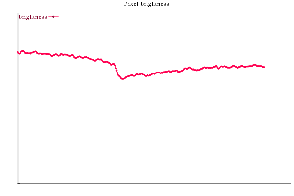
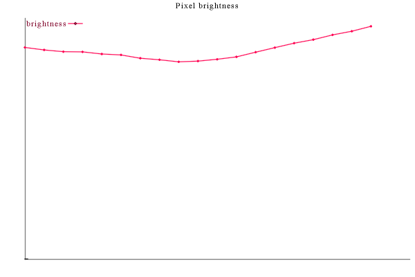
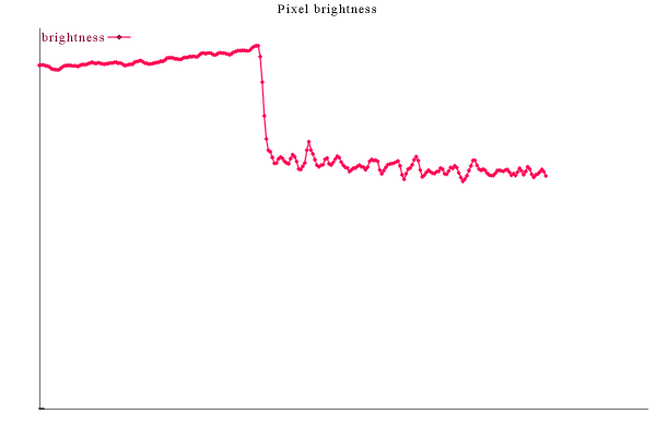
If we just look at the numbers from a point on one side of the edge to a point on the other side, we can see in a single graph how the surfaces on either side of the edge darken as they approach it.
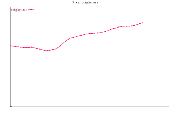
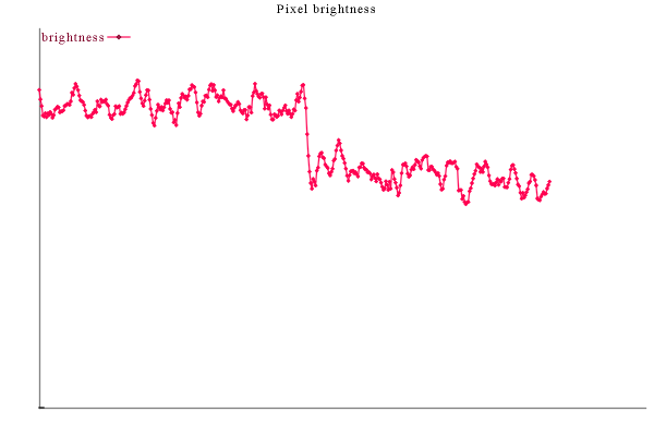
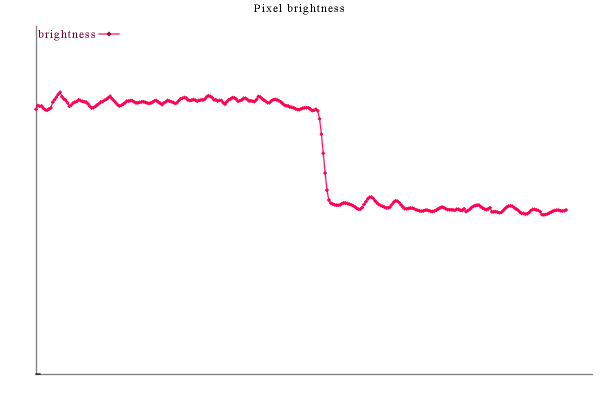
For example, if we sample pixels on a line crossing the edge between (c) and (d) and then graph them, we get:

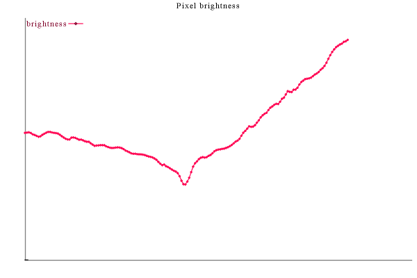
The code used to generate the above graph appears in Appendix A.
Note that this is a graph of pixel values (actually 5x5 box filter averaged over all three channels), so this is a graph of sRGB brightness (or whatever it really is; I'll just say sRGB henceforth), not linear light values. All graphs are 0-based, so you can judge ratios of brightness values by the ratios of their height above the baseline. (You can mentally square those ratios to get an approximate light-linear ratio. I'm begging off on doing light-linear graphs just because this is already way more work than I should have ever done on something I'm never going to work on myself.)
On the left we can see the lighting darkens more quickly as we approach the edge, whereas the righthand side shows a much more linear climb (because it's traversing through the soft shadow, presumably). There's also a very pronounced dip at the very edge, but it's unclear what this is due to. (It might not even be a lighting effect; perhaps the corner is dirtier.)
The edge between (a) and (d) looks similar when graphed.
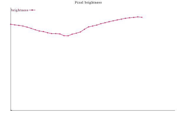
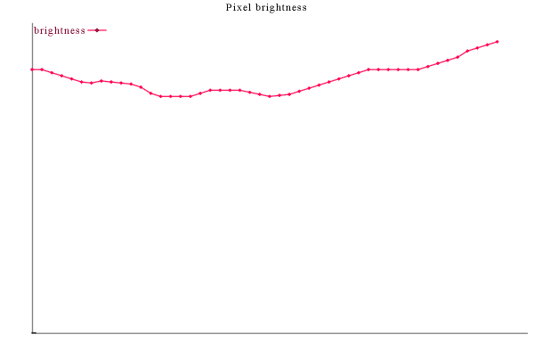
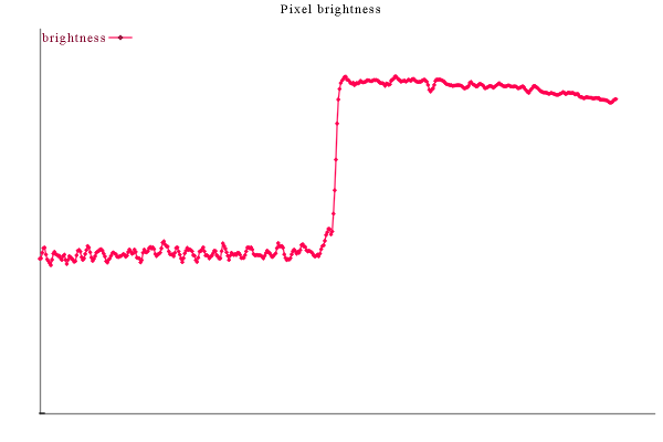
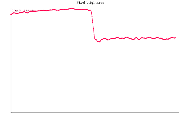
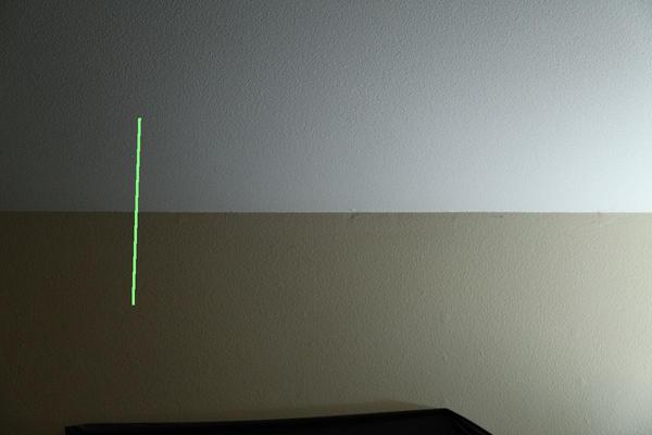
But let's look at the edge between (a) and (c), which is in theory less exaggerated, and more like a "real world AO" effect, in that it has the most-indirected lighting.
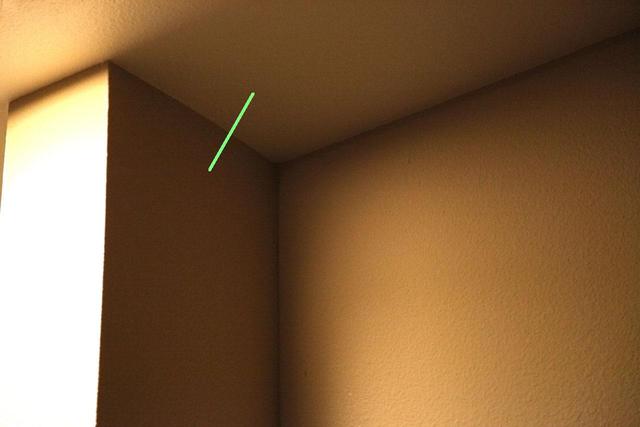
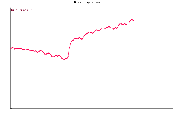
The graph here is from bottom-to-top.
Again we can see a clear darkening towards the edge, but the effect is significantly reduced in magnitude. There's no downward dip at the center.
Some care must be exercised in comparing graphs. Ideally, the line segments would be split in two and each half would be perpendicular to the edge in world space, and we would account for foreshortening. Instead I'm using a single line which may foreshorten differently, and the graph is autoscaled to however many pixels are covered, which may not always be consistent. In particular, the second line above definitely looks less perpendicular than the first, but I'm not sure how big an effect this is.
By the way, to help understand scale: wall (c) is 13.5 inches wide. So the green line segment on it (displayed in the left half of the graph) is probably around 4 inches long, and the same range of brightness it traverses in those 4 inches would probably only take 3 inches if the line were perpendicular to the edge.
Again, someone else who's actually working in this area should do it more properly. I just want to call attention to the issue.
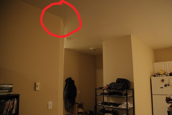
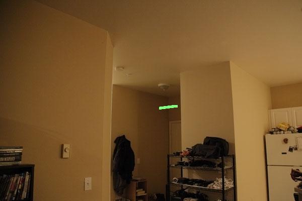
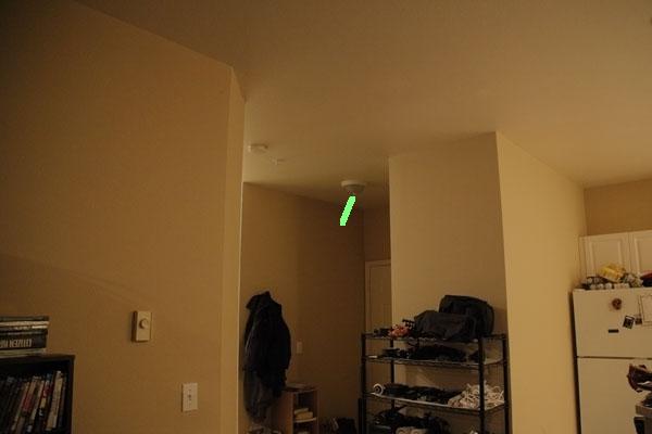
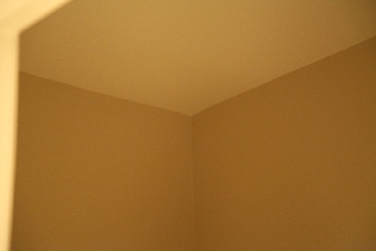
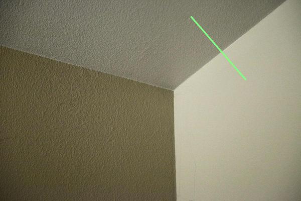
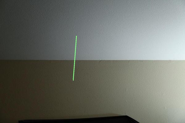
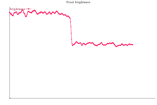
Let's take a look at three corners visible in the following image:

I've taken separate photographs that are zoomed in for closer shots, which we'll use to actually sample the edges.
The only truly direct light on this is from the left; the principal lighting appears to be lighting from the same recessed lamp on the ceiling; I'm not sure how indirect it is. In real life the area is moderately dark. (Note also that the image corners are darkened due to camera lens vignetting due to the large zoom factor.)
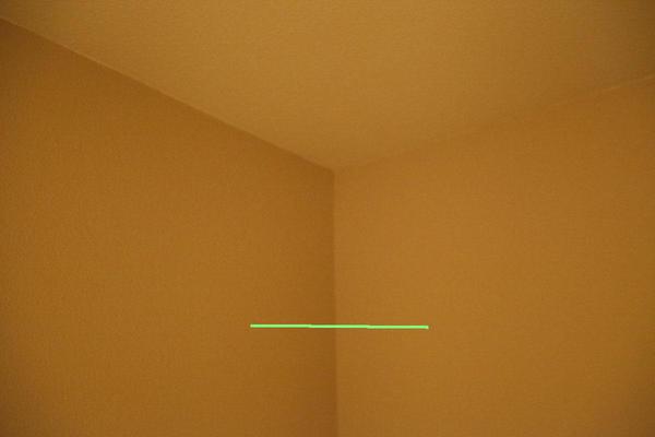
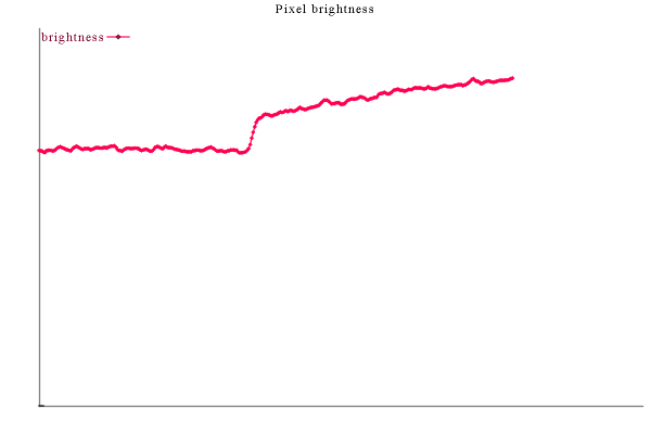
Here's what the pixels between the wall and the ceiling look like:
The ceiling darkens slightly as it approaches the edge, but the wall is still brightening).
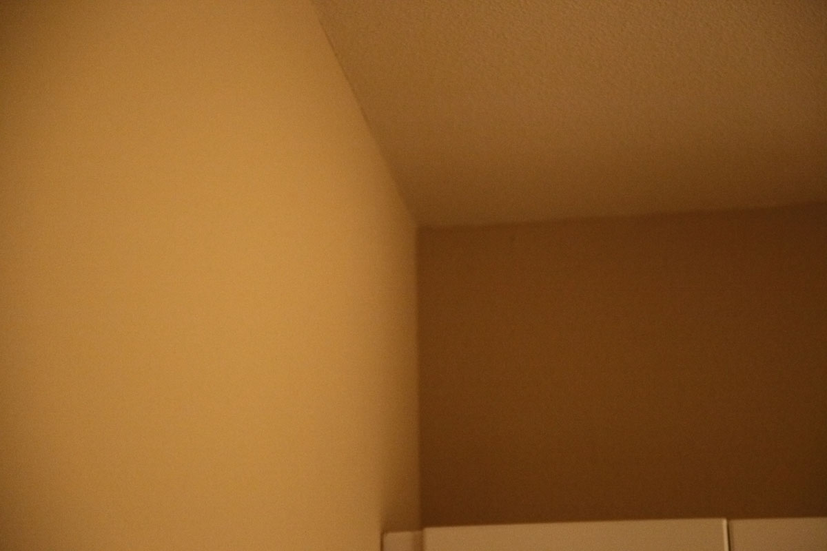
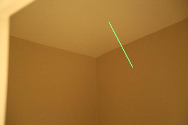
Here's a longer exposure of this corner which is moderately lit although almost entirely indirectly lit, as you can see from the shadows above.

This doesn't really look to me like it's just brighter version of the above image; it seems like the walls darken a lot less significantly. Fortunately, we can check the numbers.


These are much flatter than I expected; it looks like while there's some darkening of the left wall, I guess a lot of the darkening I'm "seeing" is really just Mach banding. (But don't forget the difference between sRGB and linear light, which means the linear light darkening is more significant than the graph shows.)
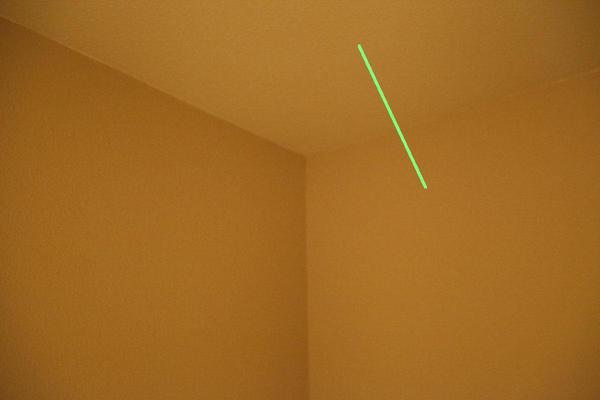
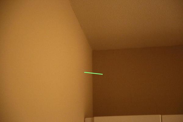
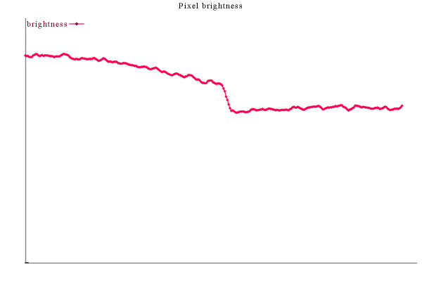
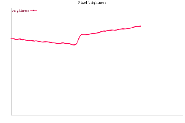
But now let's go back to the long shot and measure the numbers there:


(This last line is drawn top-to-bottom, right-to-left, so the brighter bulge on the left
of the graph is due to the 5x5 sampling picking up the highlight on the light fixture.)
And sure enough, the darkening is way less prominent here than I think it is visually. I have no idea why it looks like it's a more significant darkening factor to me. Maybe going to light-linear would make it clearer.

This space above the cabinet above the refrigerator seems to be predominantly indirectly lit. However, note that the left wall and ceiling are severely foreshortened and significantly foreshortened respectively, so the rapid darkening we see here is actually much more gradual in worldspace.
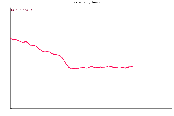

Again, the effect on the back wall is extremely mild (the mach band effect is much stronger), while the effect on the left wall and ceiling is very clear (although enchanced by the foreshortening). Note that the Mach band effect only happens because the other wall is brighter; if the back wall were painted a brighter color than the other walls it probably wouldn't happen at all (as it didn't in the "left corner" above).
(BTW, you can verify that things are Mach banding effects by covering up one side of the edge and seeing if the edge-darkening effect goes away. This is definitely going on for me with the back wall.)
By the way, I also tested graphing the output of a 3x3 box-filter isntead of 5x5, and the results looked similar.
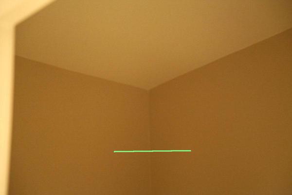
Here we'll peek into a dark bathroom.
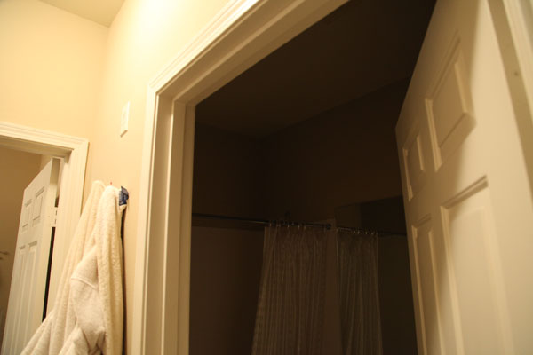
That sure looks like some darkening along the edges.
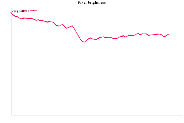
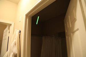
Zooming in, with a 1/8th of a second exposure, gives us:
Where'd the darkening go? We run the numbers:

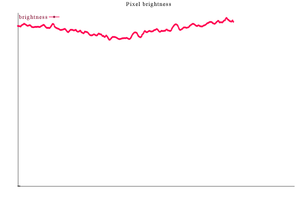
There's some darkening going on, but it ain't much. Once again, let's go back to the original image and pull the numbers from those and compare.

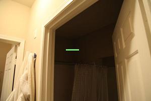

The first two seem a bit different, but this could be due to the difference of the length of the line segments in worldspace. Hmm.
Obviously some of the fall-off towards the edges will be due to direct lighting fall-off. But is there some more "extra" fall-off towards the edge that we should simulate using SSAO?

I say no.
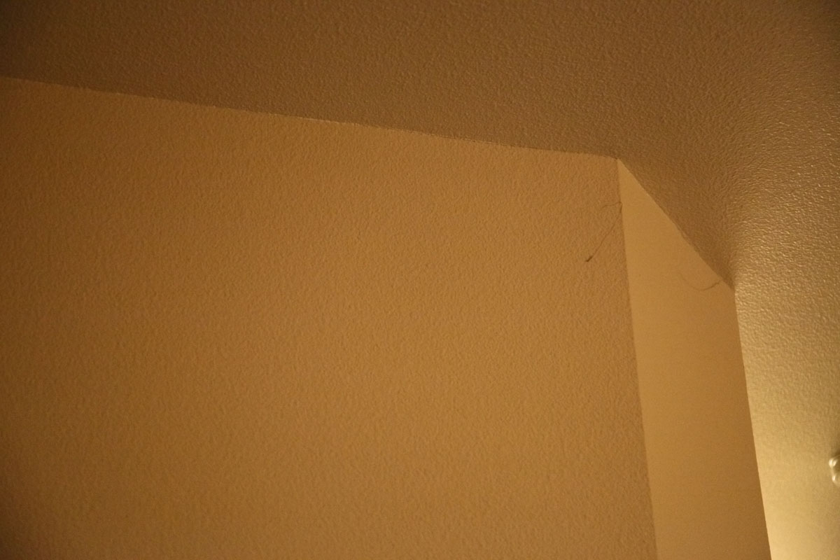
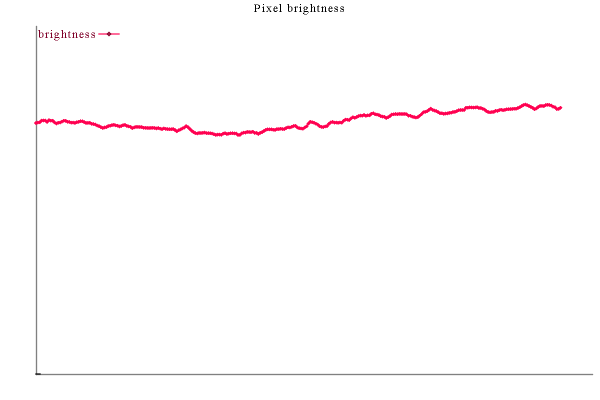
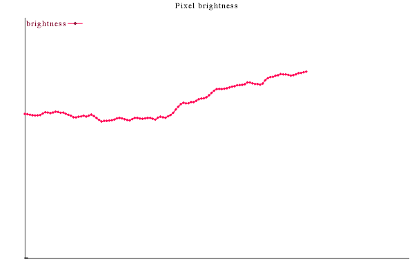
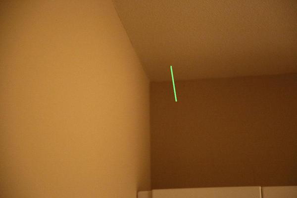
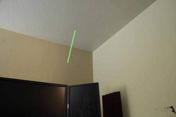
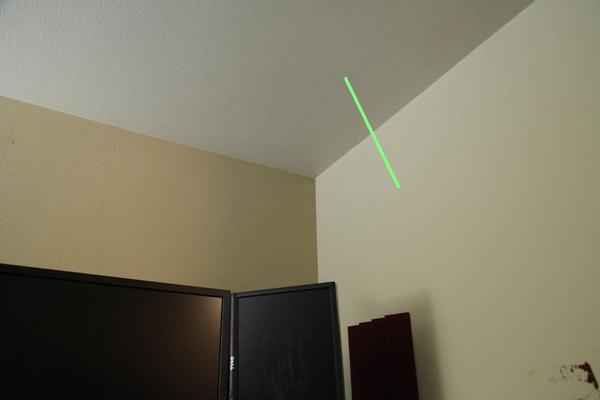
Here's a corner above where I'm typing this right now.

This is the first corner I look at when I'm sitting at my computer and I think "what does a corner really look like?"
Answer: not like crappy AO darkening!
The primary light is a floor lamp far to the left; because the right wall is facing it the right wall is brighter.
There's an obvious darkening of the left wall above the boundary between the monitors; this is a shadow from a second light (everything right of it, meaning all the lines sampled below, are in shadow from that second light).
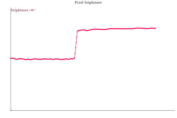
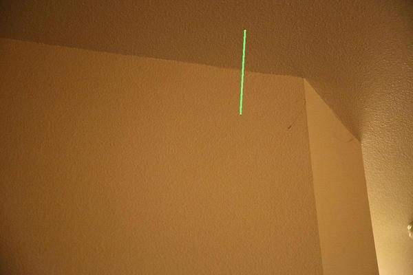
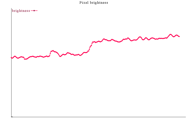
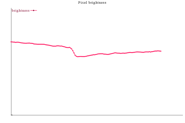
The last line segment is being graphed bottom to top. The tiny peak
at the edge is probably because the edge between the two walls sometimes
has white paint showing through, so it's not a lighting effect.
Note that there is basically no corner-darkening effect. The ceiling actually brightens as it approaches the right wall, presumably because the right wall is brighter at the top because of the direct lighting on it.
Only the line along the left wall as it approaches the ceiling shows any significant darkening that might be best simulated by AO. But while AO might make that part of the line look more realistic, it will make the other five look less realistic.
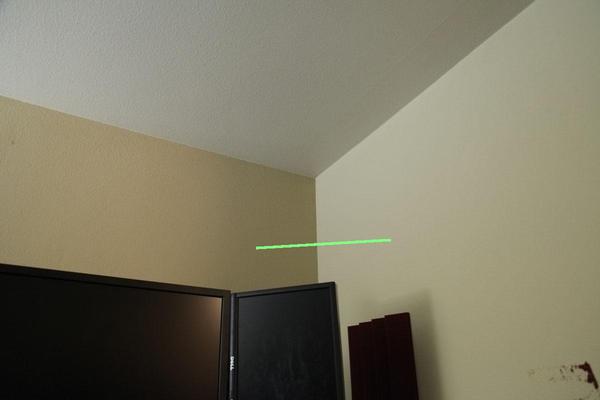
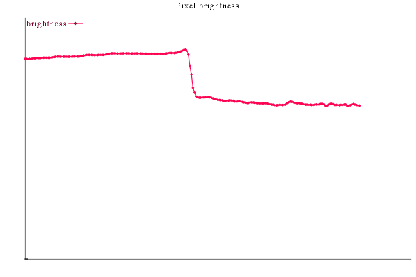
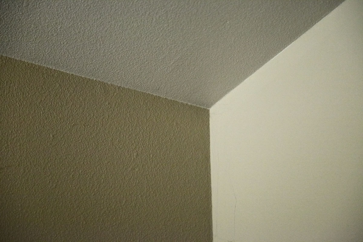
Just for reference, here's a closeup of the corner.
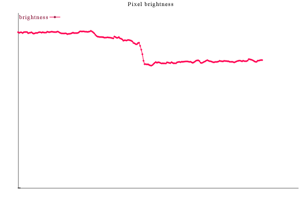
And the graphs are still pretty similar (although noisier due to the visible texture, and these cover a slightly smaller region, though I used longer lines to try to compensate):

Again I invite you to cover the brighter side of each edge to see whether the edge darkening is real or a perceptual artifact.
The light is on the right. As you go left, it gets darker, and the contribution due to ambient light should become a larger and larger fraction. Can we see an increasing effect of AO-esque darkening?

The vertical axis of the graph is autoscaled (the baseline is always 0). So if there were a meaningful edge-darkening of "ambient" light going on (by which I mean if the AO corner-darkening model was at all a reasonable approximation of the real world), we'd expect to see an increasing amount of darkening towards the edge as the measured region goes into darkness. What I see in the above graph is that the ceiling's edge-darkening does increase (it goes from getting slightly brighter at the edge in the first graph to getting slight darker in the last), but the wall seems to show an an essentially opposite effect (going from just barely darkening at the edge on the first graph, to increasing in the second, to being flat in the third).
There is an edge-darkening effect along concave boundaries between walls (surfaces), but it is subtle and only happens some of the time. The only time a strongly prominent edge-darkening occurs is when the facing surface is itself already significantly darkening at the edge for another reason (such as soft shadows).
And that's probably not what your SSAO is doing.
Here's the code used to generate the graphs from a list of points and image filenames.
#define STB_IMAGE_WRITE_IMPLEMENTATION
#include "stb_image_write.h"
#define STBI_NO_WRITE  // disable writer in old version of stb_image
#include "stb_image.c"
#define STB_PLOT_IMPLEMENTATION
#include "stb_plot.h" // unfinished, unreleased line graph library
#define STB_DEFINE
#include "stb.h"

int main(int argc, char **argv)
{
   int i,n;
   char **data = stb_stringfile("c:/imv_log.txt", &n);
   for (i=0; i < n; i += 2) {
      int w,h;
      int x0,y0,x1,y1,j,len;
      uint8 *pixels;
      char file1[999], file2[999], name[999];

      stbplot_dataset *ds = stbplot_dataset_create();
      stbplot_variable *v = stbplot_dependent_variable(ds, "brightness");

      if (  sscanf(data[i  ], "%d%d%s", &x0,&y0, file1) != 3
         || sscanf(data[i+1], "%d%d%s", &x1,&y1, file2) != 3)
         stb_fatal("Error on line %d\n", i+1);
      if (strcmp(file1, file2)) stb_fatal("Mismatch %1 vs %2\n", i+1, i+2);

      pixels = stbi_load(file1, &w, &h, NULL, 3);
      if (x0 >= w || y0 >= h || x1 >= w || y1 >= h) stb_fatal("Bad point in %d/%d", i+1,i+2);

      len = max(abs(x1-x0),abs(y1-y0));
      for (j=0; j <= len; ++j) {
         int dx,dy,c,sum=0;
         int x = (int) stb_linear_remap(j,0,len,x0,x1);
         int y = (int) stb_linear_remap(j,0,len,y0,y1);
         for (dx = -2; dx <= 2; ++dx)
            for (dy = -2; dy <= 2; ++dy)
               for (c=0; c < 3; ++c)
                  sum += pixels[(y+dy)*3*w + (x+dx)*3 + c];
         stbplot_add_value(j, v, (double) sum / (9*3));
      }

      stb_splitpath(name, file1, STB_FILE);
      stbplot_plot(stb_sprintf("c:/temp2/graph_%s_%d.bmp", name, i/2+1),
                   ds, "Pixel brightness", 600, 400, 1);
      stbplot_dataset_destroy(ds);

      // overdraw the highlight
      for (j=0; j <= len; ++j) {
         int dx, dy, c, color[3] = { 128,255,128 };
         int x = (int) stb_linear_remap(j,0,len,x0,x1);
         int y = (int) stb_linear_remap(j,0,len,y0,y1);
         for (dx = -2; dx <= 2; ++dx)
            for (dy = -2; dy <= 2; ++dy)
               for (c=0; c < 3; ++c)
                  pixels[(y+dy)*3*w + (x+dx)*3 + c] = color[c];
      }
      stbi_write_png(stb_sprintf("c:/temp2/highlight_%s_%d.png", name, i/2+1),
                     w,h,3,pixels,w*3);
   }
   return 0;
}
I got lucky and it worked correctly on after the first successful compile. It never hit the error cases.
Does that mean I shouldn't have bothered writing the error cases for such a small,
single-use program? Hmm.